Thermostat Wiring Guide – How To Do it Right
In this article, I am going to explain to you how to wire a thermostat in your home. This information is designed to help you understand how the thermostat functions, how to set up a new thermostat, thermostat wiring, and configuring it to work with your current HVAC. I won’t go very deep into the details because I understand my audience is made of mostly those who want to try a DIY and not technicians.
 If you haven’t purchased a thermostat yet, you might want to read my article on reasons why you need to buy a smart thermostat first.
A thermostat provides a control point for your heating and cooling systems. It is a point where you can either switch on or off your heating and cooling systems. Advanced thermometers provide options to adjust the temperature of your home to a point that fits you best.
To wire a thermostat, you must check your HVAC system since different systems require different ways of wiring. The majority of homes nowadays have an A/C unit and a furnace that is either powered by gas, oil, or electricity. Thermostat wiring on these systems can be very similar. However, a heat pump thermometer wiring is a little different.
Before I show you how to wire your thermostat, you must be comfortable with handling the wires and sure that you can do the job. Otherwise, I’d recommend that you just find a technician to help you accomplish the task. Not only is it wise, but can also save you from tampering with your thermostat.
I will show you how to wire your thermostat in the two scenarios that I have mentioned above. I will also include thermostat wiring diagrams to help you understand the color codes. One thing you have to note is that sometimes the color codes I give won’t resemble what that of your thermostat wiring. In this case, whoever wired your thermostat may not have followed these standards and you have to determine the way it is wired before you disconnect.
Wiring a home thermostat
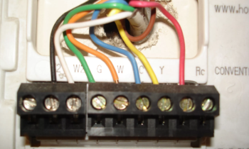
Begin by writing down the color codes and which terminal they go to. This is essential because even if the wires don’t match the required color codes, you can at least, know how you will wire the new thermostat.
If you are changing from a non-programmable thermostat to a programmable one, then everything should go pretty well because most HVAC systems are compatible. However, if you are dealing with a heat pump system, you’ll have to determine through research whether it will work or it needs more circuits.
Thermostat Wiring color codes
I have created the chart below to help you determine the common terminals you should expect in a thermostat and the respective color codes that are connected to them. Not all thermostats have all these connection points, so you just have to follow the connection points of your particular unit.
| Terminal | Color | Signal-Type | Description |
|---|---|---|---|
| C | Black/Blue | 24 Vac Common | Common of 24 Vac transformer |
| G | Green | Switched power for fan | Signal to turn on fan |
| Y | Yellow | Switched power (Cooling) | Signal to turn on cooling system |
| R/V | Red | 24 Vac transformer power | Power side of 24 Vac transformer |
| RH or 4 | Red | 24 Vac for heat | 24 Vac power before heat switch |
| RC | Red | 24 Vac for cool | 24 Vac power before cool switch |
| W | White | Switched power (heating) | Signal to turn on heating system |
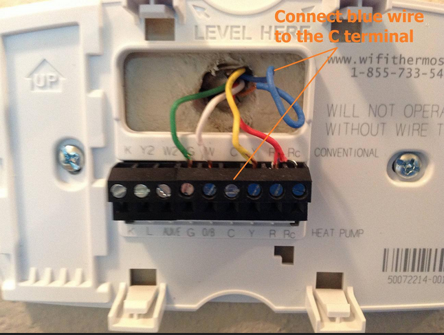
You can also read more about the C wire here
Heat pumps/multi-stage heating and cooling systems are wired a bit differently.
Heat pump thermostat wiring diagram
| Terminal | Color | Signal-Type | Description |
|---|---|---|---|
| Y2 | Varies | Switched power -2nd stage cooling | 2nd stage cooling signal for compressor |
| W2 | Varies | Switched power -2nd stage heating | 2nd stage heating also used as emergency heat |
| E | Varies | Emergency heat | Dedicated emergency heat |
| O | Orange | Reversing valve | Reversing dynamics of the heat pump |
How to connect a basic 4-wire thermostat
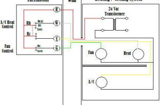
Using the color code chart above, I will show you how to connect a basic 4-wire A/C thermostat that utilizes 5 terminals only. The following are the wires that you’ll use in this connection;
- RC –Red Wire (power 24 Vac)
- G –Green Wire (control fan ON)
- RH/4 –Red Wire (Powered 24 Vac)
- Y –Yellow Wire (Cooling enable)
- W –White Wire (Heating enable)
The diagram below is pretty straightforward and shall show you how to connect the thermostat seamlessly. Although your connections may look a bit different on the thermostat, you just need basic wiring ideas and how home thermostats work. A good starting point would be to connect the RED 24 Vac transformer cable to the RC ad RH/4 terminal. In some thermostats, there’s a dedicated R terminal that jumpers to RH/4 and RC terminals internally. The other cables, the G, W, and Y should be easy to connect.
If your connection looks like the one below, it is easy to connect to a programmable or non-programmable thermostat. The difference between the two is the lack of the R connection only.
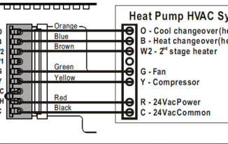
For those using a heat pump system, you’ll find the connection to be very different. Color codes may vary, but the concept should be the same. If you are changing from a heat pump thermostat to a programmable one, make sure that it is compatible before making the switch. Below is a diagram that will help in the connection.
Also, here is a video guide.